 Kia Sorento: Sub Frame Removel
Second Generation XM (2011-2025) / Kia Sorento XM 2011-2025 Service Manual / Suspension System / Front Suspension System / Sub Frame Removel
| 1. |
Remove the front wheel and tire (A) from front hub .
|
| 2. |
Disconnect the stabilizer link(B) with the front strut assembly(A)
after loosening the nut.
|
| 3. |
Remove the sprit pin and castle nut and then disconnect the tie-rod
end (A) from the front knuckle.
|
| 4. |
Loosen the bolt & nut and then remove the lower arm (A).
|
| 5. |
Loosen the bolt (A) and then disconnect the universal joint assembly
from the pinion of the steering gear box.
|
| 6. |
Remove the under cover.
(Refer to Engine Mechanical System - "Engine Room Under Cover")
|
| 7. |
Loosen the bolt (A,B) and then remove the upper roll rod bracket.
|
| 8. |
Remove the roll rod stopper bolt (A).
|
| 9. |
Disconnect the muffler rubber hanger (A).
|
| 10. |
Loosen the bolts & nuts and then remove the sub frame.
|
| 11. |
Loosen the bolt (A-4ea) and then remove the stabilizer bar (B)
from the sub frame.
|
| 12. |
Loosen the bolt and then remove the protector (A).
|
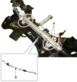
| 13. |
Remove the steering gearbox (B) from the cross member by loosening
the mounting bolt (A-4ea).
|
| 14. |
Loosen the nut (A-2ea) and then remove the sub frame damper (B).
|
| 15. |
Remove the front lower arm.
(Refer to Front Suspension System - "Front Lower Arm")
|
| 16. |
Loosen the bolt (A-2ea) and then remove the roll rod stopper (B)
from the sub frame (C).
|
| 17. |
Installation is the reverse of removal.
|
| 18. |
Check the wheel Alignment.
(Refer to Tires/Wheels - "Alignment")
|
 Front Stabilizer Bar Inspection
1.
Check the bushing for wear and deterioration.
2.
Check the front stabilizer bar for deformation.
...
See also:
Removal
1.
Turn the ignition switch OFF and disconnect the battery negative
(-) cable.
2.
Disconnect the crankshaft position sensor connector (A).
...
Component Location (1)
1. Smart key unit
2. Interior antenna 3
3. Interior antenna 2
4. Interior antenna 1
5. Buzzer
...
Circuit Diagram
Circuit Diagram (2)
Circuit Diagram (3)
...
Copyright © www.ksmanual.com 2014-2025


