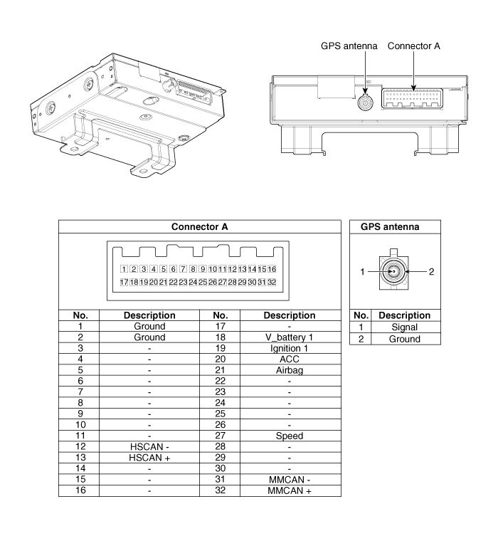
 Kia Sorento: Telemetics Unit (TMU) Component
Second Generation XM (2011-2025) / Kia Sorento XM 2011-2025 Service Manual / Body Electrical System / MTS System / Telemetics Unit (TMU) Component

Connector Pin Specification
| No. |
Pin Name |
Type |
From |
To |
Description (Wiring Spec.) |
| 1 |
GND |
DC Ground |
TMU |
Battery |
Connected to battery ground |
| 2 |
GND |
DC Ground |
TMU |
Battery |
Connected to battery ground |
| 3 |
- |
- |
- |
- |
- |
| 4 |
- |
- |
- |
- |
- |
| 5 |
- |
- |
- |
- |
- |
| 6 |
- |
- |
- |
- |
- |
| 7 |
- |
- |
- |
- |
- |
| 8 |
- |
- |
- |
- |
- |
| 9 |
- |
- |
- |
- |
- |
| 10 |
- |
- |
- |
- |
- |
| 11 |
- |
- |
- |
- |
- |
| 12 |
HS CAN (-) |
Data I/O |
BUS |
BUS |
High Speed CAN bus low |
| 13 |
HS CAN (+) |
Data I/O |
BUS |
BUS |
High Speed CAN bus high |
| 14 |
- |
- |
- |
- |
- |
| 15 |
- |
- |
- |
- |
- |
| 16 |
- |
- |
- |
- |
- |
| 17 |
- |
- |
- |
- |
- |
| 18 |
V battery 1 |
DC Input |
Battery |
TMU |
DC level input from battery Supply power to TMU |
| 19 |
Ignition 1 |
Data Input |
Junction Box |
TMU |
Vehicle Key mode status |
| 20 |
ACC |
Data Input |
Junction Box |
TMU |
Vehicle Key mode status |
| 21 |
Airbag |
Data Input |
ACU |
TMU |
Airbag status data from ACU |
| 22 |
- |
- |
- |
- |
- |
| 23 |
- |
- |
- |
- |
- |
| 24 |
- |
- |
- |
- |
- |
| 25 |
- |
- |
- |
- |
- |
| 26 |
- |
- |
- |
- |
- |
| 27 |
Speed |
Data Input |
- |
TMU |
GPS Calibration (UVO ONLY) |
| 28 |
- |
- |
- |
- |
- |
| 29 |
- |
- |
- |
- |
- |
| 30 |
- |
- |
- |
- |
- |
| 31 |
MM CAN (-) |
Data I/O |
BUS |
BUS |
Low Speed CAN bus low |
| 32 |
MM CAN (+) |
Data I/O |
BUS |
BUS |
Low Speed CAN bus high |
 Description
The Vehicle Information System is a Telematics service that ensures comfortable
and enjoyable driving by providing safety, security, and vehicle diagnostic
information, with the option of usi ...
 Telemetics Unit (TMU) Removal
•
Take care not to scratch the crash pad and related parts.
...
See also:
Driver Airbag (DAB) Module and Clock Spring Components
1. Driver Airbag (DAB)
2. Steering Wheel
3. Clock Spring
...
Using the USB device
To use an external USB device, make sure the device is not connected when
starting up the vehicle. Connect the device after starting up.
If you start the engine when the USB device is connected ...
Copyright © www.ksmanual.com 2014-2025
