 Kia Sorento: Inspection
Front Door Lock Actuator
| 1. |
Remove the front door trim.
(Refer to Body - "Front door")
|
| 2. |
Remove the front door module.
(Refer to Body - "Front door")
|
| 3. |
Disconnect the connectors from the actuator.
|
| 4. |
Check actuator operation by connecting power and ground according
to the table. To prevent damage to the actuator, apply battery voltage
only momentarily.
|
Rear Door Lock Actuator
| 1. |
Remove the rear door trim.
(Refer to Body - "Rear door")
|
| 2. |
Remove the rear door module.
(Refer to Body - "Rear door")
|
| 3. |
Disconnect the connectors from the actuator.
|
| 4. |
Check actuator operation by connecting power and ground according
to the table. To prevent damage to the actuator, apply battery voltage
only momentarily.
|
Tailgate Lock Actuator Inspection
| 1. |
Remove the tailgate trim.
(Refer to Body - "Tailgate")
|
| 2. |
Disconnect the 4P connector from the actuator.
|
| 3. |
Check actuator operation by connecting power and ground according
to the table. To prevent damage to the actuator, apply battery voltage
only momentarily.
|
Front Door Lock Switch
| 1. |
Remove the front door trim.
(Refer to Body - "Front door")
|
| 2. |
Remove the front door module.
(Refer to Body - "Front door")
|
| 3. |
Disconnect the connectors from the actuator.
|
| 4. |
Check for continuity between the terminals in each switch position
when inserting the key into the door according to the table.
|
Rear Door Lock Switch
| 1. |
Remove the rear door trim.
(Refer to Body - "Rear door")
|
| 2. |
Remove the rear door module.
(Refer to Body - "Rear door")
|
| 3. |
Disconnect the connectors from the actuator.
|
| 4. |
Check for continuity between the terminals in each switch position
according to the table.
|
Tailgate Switch
| 1. |
Remove the tailgate trim.
(Refer to Body - "Tailgate")
|
| 2. |
Disconnect the 4P connector from the actuator.
|
| 3. |
Check for continuity between the terminals in each switch position
according to the table.
|
Door Switch
Remove the door switch and check for continuity between the terminals.


Hood Switch
| 1. |
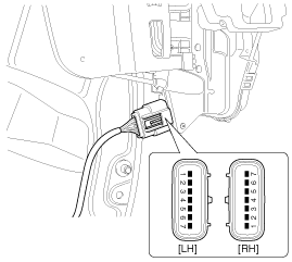
Disconnect the connector (A) and bolt from the hood switch.
|
| 2. |
Check for continuity between the terminals and ground according
to the table.
[2P Connector]
[1P Connector]
|
Burglar Horn
| 1. |
Remove the burglar horn after removing a bolt and disconnect the
2P connector from the burglar horn.
|
| 2. |
Test the burglar horn by connecting battery power to the terminal
1 and ground the terminal 2.
|
| 3. |
The burglar horn should make a sound. If the burglar horn fails
to make a sound replace it.
|
 Description
Burglar Alarm State [B/A State]
B/A State
Description
DISARM
1.
In "DISARM" state, no vehicle start inhibition. So, whe ...
 Transmitter Inspection
1.
Check that the red light flickers when the door lock or unlock
button is pressed on the transmitter.
2.
Remove the battery (A) and check ...
See also:
Adjustment
After replacing ETC module or ECM, the ETC adaptive value must be reset
/ relearned according to the following procedure.
1.
Check DTC(s) and clear if exist.
...
On-vehicle Inpection
•
First of all, check for DTCs. If a DTC is present, perform
troubleshooting in accord ...
Roof Trim Replacement
Sunvisor Replacement
1.
Remove the sunvisor cover (A).
2.
After loosening the mounting screws, then remove the sunvisor
(B) and retaine ...
Copyright В© www.ksmanual.com 2014-2024


