 Kia Sorento: Relay Box (Engine Compartment) Inspection
Second Generation XM (2011-2025) / Kia Sorento XM 2011-2025 Service Manual / Body Electrical System / Fuses And Relays / Relay Box (Engine Compartment) Inspection
| 1. |
Disconnect the negative (-) battery terminal.
|
| 2. |
Pull out the relay from the engine compartment relay box.
|
Power Relay (Type A)
Check for continuity between the terminals.
A : Start relay #1
B : Windshield deicer relay
C : Power outlet relay
D : Burglar alarm horn relay
E : Head lamp RH relay
F : IGN 1 relay
G : IGN 2 relay
H : Rear glass defogger relay
I : Horn relay
J : Blower relay
| 1. |
There should be continuity between the No.30 and No.87 terminals
when power and ground are connected to the No.85 and No.86 terminals.
|
| 2. |
There should be no continuity between the No.30 and No.87 terminals
when power is disconnected.
|
Power Relay (Type B)
Check for continuity between the terminals.
A : Wiper relay (Low)
B : Start relay #2 (W/O immo./smart key)/ ACC relay (With smart key)
| 1. |
There should be continuity between the No.30 and No.87 terminals
when power and ground are connected to the No.85 and No.86 terminals.
|
| 2. |
There should be continuity between the No.30 and No.87a terminals
when power is disconnected.
|
| 3. |
There should be no continuity between the No.30 and No.87 termianls
when power is disconnected.
|
Power Relay (Type C)
Check for continuity between the terminals.
A : Condenser pan relay #1
| 1. |
There should be continuity between the No.30 and No.87 terminals
when power and ground are connected to the No.85 and No.86 terminals.
|
| 2. |
There should be no continuity between the No.30 and No.87 terminals
when power is disconnected.
|
Fuse
| 1. |
Be sure there is no play in the fuse holders, and that the fuses
are held securely.
|
| 2. |
Are the fuse capacities for each circuit correct?
|
| 3. |
Are there any blown fuses?
If a fuse is to be replaced, be sure to use a new fuse of the
same capacity. Always determine why the fuse blew first and completely
eliminate the problem before installing a new fuse.
|
Multi Fuse

|
Replacement of EMS block
| 1. |
Disconnect the negative(-) battery terminal.
|
| 2. |
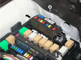
Push 3 hooks in the engine room relay box out to the arrow direction
and put up the EMS box assembly (A).
|
| 3. |
Disconnect the connector and remove the EMS box assembly (A).
|
See also:
Filler-Neck Assembly Installation
1.
Install in the reverse order of removal.
Filler-neck assembly bracket
installation nut :
3.9 ~ 5.9 N.m (0.4 ~ 0.6 kgf.m, 2.9 ~ ...
Parking Brake Assembly Installation
Parking Brake Shoe
1.
Install the shoe hold down pin (A) and spring (B) by pressing
and rotating the spring.
2.
Install the ope ...
Specifications
Direct control VFS[OD/C]
▷ Control type : Normal high type
Control Pressure kpa
(kgf/cm², psi)
539.370 ~ 0 ( 5.5 ~ 0, 78.23 ~ 0)
Current value(mA)
...
Copyright © www.ksmanual.com 2014-2025


